


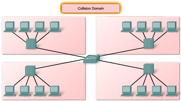
Broadcast and collision domain


Switch Forwarding Methods
Switches can operate in different modes that can have both positive and negative effects. In the past, switches used one of the following forwarding methods for switching data between network ports: store-and-forward or cut-through switching. Switches can operate in different modes that can have both positive and negative effects. However, store-and-forward is the sole forwarding method used on current models of Cisco Catalyst switches.
Store-and-Forward Switching
In store-and-forward switching, when the switch receives the frame, it stores the data in buffers until the complete frame has been received. During the storage process, the switch analyzes the frame for information about its destination. In this process, the switch also performs an error check using the Cyclic Redundancy Check (CRC) trailer portion of the Ethernet frame.
CRC uses a mathematical formula, based on the number of bits (1s) in the frame, to determine whether the received frame has an error. After confirming the integrity of the frame, the frame is forwarded out the appropriate port toward its destination. When an error is detected in a frame, the switch discards the frame. Store-and-forward switching is required for Quality of Service (QoS)
Cut-through Switching
In cut-through switching, the switch acts upon the data as soon as it is received, even if the transmission is not complete. The switch buffers just enough of the frame to read the destination MAC address so that it can determine to which port to forward the data. The destination MAC address is located in the first 6 bytes of the frame following the preamble. The switch looks up the destination MAC address in its switching table, determines the outgoing interface port, and forwards the frame onto its destination through the designated switch port. The switch does not perform any error checking on the frame. Because the switch does not have to wait for the entire frame to be completely buffered, and because the switch does not perform any error checking, cut-through switching is faster than store-and-forward switching. However, because the switch does not perform any error checking, it forwards corrupt frames throughout the network. The corrupt frames consume bandwidth while they are being forwarded. The destination NIC eventually discards the corrupt frames. There are two variants of cut-through switching:
- Fast-forward switching: Fast-forward switching offers the lowest level of latency. Fast-forward switching immediately forwards a packet after reading the destination address. Because fast-forward switching starts forwarding before the entire packet has been received, there may be times when packets are relayed with errors. This occurs infrequently, and the destination network adapter discards the faulty packet upon receipt. In fast-forward mode, latency is measured from the first bit received to the first bit transmitted. Fast-forward switching is the typical cut-through method of switching.
- Fragment-free switching: In fragment-free switching, the switch stores the first 64 bytes of the frame before forwarding. Fragment-free switching can be viewed as a compromise between store-and-forward switching and cut-through switching. The reason fragment-free switching stores only the first 64 bytes of the frame is that most network errors and collisions occur during the first 64 bytes. Fragment-free switching tries to enhance cut-through switching by performing a small error check on the first 64 bytes of the frame to ensure that a collision has not occurred before forwarding the frame. Fragment-free switching is a compromise between the high latency and high integrity of store-and-forward switching, and the low latency and reduced integrity of cut-through switching.

Symmetric and Asymmetric Switching
LAN switching may be classified as symmetric or asymmetric based on the way in which bandwidth is allocated to the switch ports.
Symmetric switching provides switched connections between ports with the same bandwidth, such as all 100 Mb/s ports or all 1000 Mb/s ports. An asymmetric LAN switch provides switched connections between ports of unlike bandwidth, such as a combination of 10 Mb/s, 100 Mb/s, and 1000 Mb/s ports. The figure shows the differences between symmetric and asymmetric switching.

Memory Buffering
A switch analyzes some or all of a packet before it forwards it to the destination host based on the forwarding method. The switch stores the packet for the brief time in a memory buffer. An Ethernet switch may use a buffering technique to store frames before forwarding them. Buffering may also be used when the destination port is busy due to congestion and the switch stores the frame until it can be transmitted. The use of memory to store the data is called memory buffering. Memory buffering is built into the hardware of the switch and is not configurable.
There are two methods of memory buffering: port-based and shared memory.
Port-based Memory Buffering
In port-based memory buffering, frames are stored in queues that are linked to specific incoming and outgoing ports. A frame is transmitted to the outgoing port only when all the frames ahead of it in the queue have been successfully transmitted. It is possible for a single frame to delay the transmission of all the frames in memory because of a busy destination port.
Shared Memory Buffering
Shared memory buffering deposits all frames into a common memory buffer that all the ports on the switch share. The amount of buffer memory required by a port is dynamically allocated. The frames in the buffer are linked dynamically to the destination port. This allows the packet to be received on one port and then transmitted on another port, without moving it to a different queue.

Layer 2 and Layer 3 Switching
A Layer 2 LAN switch performs switching and filtering based only on the OSI Data Link layer (Layer 2) MAC address. A Layer 2 switch is completely transparent to network protocols and user applications. A Layer 2 switch builds a MAC address table that it uses to make forwarding decisions.
A Layer 3 switch functions similarly to a Layer 2 switch, but instead of using only the Layer 2 MAC address information for forwarding decisions, a Layer 3 switch can also use IP address information. Instead of only learning which MAC addresses are associated with each of its ports, a Layer 3 switch can also learn which IP addresses are associated with its interfaces. This allows the Layer 3 switch to direct traffic throughout the network based on IP address information. Layer 3 switches are also capable of performing Layer 3 routing functions, reducing the need for dedicated routers on a LAN

However, Layer 3 switches do not completely replace the need for routers on a network.
Routers perform additional Layer 3 services that Layer 3 switches are not capable of performing. Routers are also capable of performing packet forwarding tasks not found on Layer 3 switches, such as establishing remote access connections to remote networks and devices. Dedicated routers are more flexible in their support of WAN interface cards (WIC), making them the preferred, and sometimes only, choice for connecting to a WAN. Layer 3 switches can provide basic routing functions in a LAN and reduce the need for dedicated routers.
The Switch Boot Sequence

Basic Switch Configuration
An access layer switch is much like a PC in that you need to configure an IP address, a subnet mask, and a default gateway. To manage a switch remotely using TCP/IP, you need to assign the switch an IP address. You need to assign switch S1 an IP address. This IP address is assigned to a virtual interface called a virtual LAN (VLAN), and then it is necessary to ensure the VLAN is assigned to a specific port or ports on the switch. The default configuration on the switch is to have the management of the switch controlled through VLAN 1. However, a best practice for basic switch configuration is to change the management VLAN to a VLAN other than VLAN 1. The figure illustrates the use of VLAN 99 as the management VLAN; however, it is important to consider that an interface other than VLAN 99 can be considered for the management interface.

For now, VLAN 99 is created and assigned an IP address. Then the appropriate port on switch S1 is assigned to VLAN 99.
Configure Management Interface
To configure an IP address and subnet mask on the management VLAN of the switch, you must be in VLAN interface configuration mode. Use the command interface vlan 99 and enter the ip address configuration command. You must use the no shutdown interface configuration command to make this Layer 3 interface operational

Configure Default Gateway
You need to configure the switch so that it can forward IP packets to distant networks. The default gateway is the mechanism for doing this. The switch forwards IP packets with destination IP addresses outside the local network to the default gateway. In the figure, router R1 is the next-hop router. Its IP address is 172.17.99.1.
To configure a default gateway for the switch, use the ip default-gateway command. Enter the IP address of the next-hop router interface that is directly connected to the switch where a default gateway is being configured.

Show the IP Interfaces
Use the show ip interface brief to verify port operation and status. You will practice using the switchport access vlan 99 command in a hands on lab and a Packet Tracer activity.
Configure Duplex and Speed
You can use the duplex interface configuration command to specify the duplex mode of operation for switch ports. You can manually set the duplex mode and speed of switch ports to avoid inter-vendor issues with autonegotiation.

Configure a Web Interface
Modern Cisco switches have a number of web-based configuration tools that require that the switch is configured as an HTTP server. These applications include the Cisco web browser user interface. To control who can access the HTTP services on the switch, you can optionally configure authentication. Authentication methods can be complex. You may have so many people using the HTTP services that you require a separate server specifically to handle user authentication. AAA and TACACS authentication modes are examples that use this type of remote authentication method. AAA and TACACS are authentication protocols that can be used in networks to validate user credentials. You may need to have a less complex authentication method. The enable method requires users to use the server's enable password. The local authentication method requires the user to use the login username, password, and privilege level access combination specified in the local system configuration

Managing the MAC Address Table
Switches use MAC address tables to determine how to forward traffic between ports. These MAC tables include dynamic and static addresses. The figure shows a sample MAC address table from the output of the show mac-address-table command that includes static and dynamic MAC addresses.

Note: The MAC address table was previously referred to as content addressable memory (CAM) or as the CAM table.
Dynamic addresses are source MAC addresses that the switch learns and then ages when they are not in use. You can change the aging time setting for MAC addresses. The default time is 300 seconds.
To create a static mapping in the MAC address table, use the mac-address-table static <MAC address> vlan {1-4096, ALL} interface interface-id command.
To remove a static mapping in the MAC address table, use the no mac-address-table static <MAC address> vlan {1-4096, ALL} interface interface-id command.
Verifying Switch Configuration

Back up and Restore Switch Configurations


Configure Password Options


After you set passwords to control access to the Cisco IOS CLI, you need to make sure you remember them. In case you have lost or forgotten access passwords, Cisco has a password recovery mechanism that allows administrators to gain access to their Cisco devices. The password recovery process requires physical access to the device.
Note that you may not be able to actually recover the passwords on the Cisco device, especially if password encryption has been enabled, but you are able to reset them to a new value.
To recover the password on a Cisco 2960 switch, use the following steps:
Step 1. Connect a terminal or PC with terminal-emulation software to the switch console port.
Step 2. Set the line speed on the emulation software to 9600 baud.
Step 3. Power off the switch. Reconnect the power cord to the switch and within 15 seconds, press the Mode button while the System LED is still flashing green. Continue pressing the Mode button until the System LED turns briefly amber and then solid green. Then release the Mode button.
Step 4. Initialize the Flash file system using the flash_init command.
Step 5. Load any helper files using the load_helper command.
Step 6. Display the contents of Flash memory using the dir flash command
Step 7. Rename the configuration file to config.text.old, which contains the password definition, using the rename flash:config.text flash:config.text.old command.
Step 8. Boot the system with the boot command.
Step 9. You are prompted to start the setup program. Enter N at the prompt, and then when the system prompts whether to continue with the configuration dialog, enter N.
Step 10. At the switch prompt, enter privileged EXEC mode using the enable command.
Step 11. Rename the configuration file to its original name using the rename flash:config.text.old flash:config.text command.
Step 12. Copy the configuration file into memory using the copy flash:config.text system:running-config command. After this command has been entered, the follow is displayed on the console:
Source filename [config.text]?
Destination filename [running-config]?
Press Return in response to the confirmation prompts
The configuration file is now reloaded, and you can change the password.
Step 13. Enter global configuration mode using the configure terminal command.
Step 14. Change the password using the enable secret password command.
Step 15. Return to privileged EXEC mode using the exit command.
Step 16. Write the running configuration to the startup configuration file using the copy running-config startup-config command.
Step 17. Reload the switch using the reload command.
Login Banners


Configure Telnet and SSH
Telnet is the original method that was supported on early Cisco switch models. Telnet is a popular protocol used for terminal access because most current operating systems come with a Telnet client built in. However, Telnet is an insecure way of accessing a network device, because it sends all communications across the network in clear text.
Because of the security concerns of the Telnet protocol, SSH has become the preferred protocol for remotely accessing virtual terminal lines on a Cisco device.
SSH gives the same type of access as Telnet with the added benefit of security. Communication between the SSH client and SSH server is encrypted. SSH has gone through a few versions, with Cisco devices currently supporting both SSHv1 and SSHv2. It is recommended that you implement SSHv2 when possible, because it uses a more enhanced security encryption algorithm than SSHv1.

To implement SSH, you need to generate RSA keys. RSA involves a public key, kept on a public RSA server, and a private key, kept only by the sender and receiver. The public key can be known to everyone and is used for encrypting messages. Messages encrypted with the public key can only be decrypted using the private key. This is known as asymmetric encryption. You need to generate the encrypted RSA keys using the crypto key generate rsa command.
This procedure is required if you are configuring the switch as an SSH server. Beginning in privileged EXEC mode, follow these steps to configure a hostname and an IP domain name and to generate an RSA key pair.

If you want to prevent non-SSH connections, add the transport input ssh command in line configuration mode to limit the switch to SSH connections only. Straight (non-SSH) Telnet connections are refused.
To delete the RSA key pair, use the crypto key zeroize rsa global configuration command. After the RSA key pair is deleted, the SSH server is automatically disabled. Display the status of the SSH server connections on the switch using the show ip ssh or the show ssh command.
Common Security Attacks - Mac Address Flooding


Common Security Attacks - Spoofing Attacks


Common Security Attacks - Telnet Attacks

Configure Port Security
A switch that does not provide port security allows an attacker to attach a system to an unused, enabled port and to perform information gathering or attacks. A switch can be configured to act like a hub, which means that every system connected to the switch can potentially view all network traffic passing through the switch to all systems connected to the switch. Thus, an attacker could collect traffic that contains usernames, passwords, or configuration information about the systems on the network.
All switch ports or interfaces should be secured before the switch is deployed. Port security limits the number of valid MAC addresses allowed on a port. When you assign secure MAC addresses to a secure port, the port does not forward packets with source addresses outside the group of defined addresses.
If you limit the number of secure MAC addresses to one and assign a single secure MAC address to that port, the workstation attached to that port is assured the full bandwidth of the port, and only that workstation with that particular secure MAC address can successfully connect to that switch port.
If a port is configured as a secure port and the maximum number of secure MAC addresses is reached, a security violation occurs when the MAC address of a workstation attempting to access the port is different from any of the identified secure MAC addresses.

Secure MAC Address Types
There are a number of ways to configure port security. The following describes the ways you can configure port security on a Cisco switch:
- Static secure MAC addresses: MAC addresses are manually configured by using the switchport port-security mac-address mac-address interface configuration command. MAC addresses configured in this way are stored in the address table and are added to the running configuration on the switch.
- Dynamic secure MAC addresses: MAC addresses are dynamically learned and stored only in the address table. MAC addresses configured in this way are removed when the switch restarts.
- Sticky secure MAC addresses: You can configure a port to dynamically learn MAC addresses and then save these MAC addresses to the running configuration.

Sticky MAC Address
Sticky secure MAC addresses have these characteristics:
- When you enable sticky learning on an interface by using the switchport port-security mac-address sticky interface configuration command, the interface converts all the dynamic secure MAC addresses, including those that were dynamically learned before sticky learning was enabled, to sticky secure MAC addresses and adds all sticky secure MAC addresses to the running configuration.
- If you disable sticky learning by using the no switchport port-security mac-address sticky interface configuration command, the sticky secure MAC addresses remain part of the address table but are removed from the running configuration.
- When you configure sticky secure MAC addresses by using the switchport port-security mac-address sticky mac-address interface configuration command, these addresses are added to the address table and the running configuration. If port security is disabled, the sticky secure MAC addresses remain in the running configuration.
- If you save the sticky secure MAC addresses in the configuration file, when the switch restarts or the interface shuts down, the interface does not need to relearn these addresses. If you do not save the sticky secure addresses, they are lost.
- If you disable sticky learning and enter the switchport port-security mac-address sticky mac-address interface configuration command, an error message appears, and the sticky secure MAC address is not added to the running configuration.
Security Violation Modes
It is a security violation when either of these situations occurs:
- The maximum number of secure MAC addresses have been added to the address table, and a station whose MAC address is not in the address table attempts to access the interface.
- An address learned or configured on one secure interface is seen on another secure interface in the same VLAN.
You can configure the interface for one of three violation modes, based on the action to be taken if a violation occurs. Which kinds of data traffic are forwarded when one of the following security violation modes are configured on a port:
- protect: When the number of secure MAC addresses reaches the limit allowed on the port, packets with unknown source addresses are dropped until you remove a sufficient number of secure MAC addresses or increase the number of maximum allowable addresses. You are not notified that a security violation has occurred.
- restrict: When the number of secure MAC addresses reaches the limit allowed on the port, packets with unknown source addresses are dropped until you remove a sufficient number of secure MAC addresses or increase the number of maximum allowable addresses. In this mode, you are notified that a security violation has occurred. Specifically, an SNMP trap is sent, a syslog message is logged, and the violation counter increments.
- shutdown: In this mode, a port security violation causes the interface to immediately become error-disabled and turns off the port LED. It also sends an SNMP trap, logs a syslog message, and increments the violation counter. When a secure port is in the error-disabled state, you can bring it out of this state by entering the shutdown and no shutdown interface configuration commands. This is the default mode.

Configuring Port Security


After you have configured port security for your switch, you want to verify that it has been configured correctly. You need to check each interface to verify that you have set the port security correctly. You also have to check to make sure that you have configured static MAC addresses correctly.
To display port security settings for the switch or for the specified interface, use the show port-security [interface interface-id] command.
The output displays the following:
- Maximum allowed number of secure MAC addresses for each interface
- Number of secure MAC addresses on the interface
- Number of security violations that have occurred
- Violation mode
To display all secure MAC addresses configured on all switch interfaces or on a specified interface with aging information for each, use the show port-security [interface interface-id] address command.
Disable Unused Ports
A simple method many administrators use to help secure their network from unauthorized access is to disable all unused ports on a network switch. For example, imagine that a Cisco 2960 switch has 24 ports. If there are three Fast Ethernet connections in use, good security practice demands that you disable the 21 unused ports. It is simple to disable multiple ports on a switch use the interface range command.
Nessun commento:
Posta un commento