
A WAN is a data communications network that operates beyond the geographic scope of a LAN. WANs are different from LANs in several ways. While a LAN connects computers, peripherals, and other devices in a single building or other small geographic area, a WAN allows the transmission of data across greater geographic distances. In addition, an enterprise must subscribe to a WAN service provider to use WAN carrier network services
Here are the three major characteristics of WANs:
- WANs generally connect devices that are separated by a broader geographical area than can be served by a LAN.
- WANs use the services of carriers, such as telephone companies, cable companies, satellite systems, and network providers.
- WANs use serial connections of various types to provide access to bandwidth over large geographic areas.

The Hierarchical Network Model
The hierarchical network model divides a network into three layers:
- Access layer-Grants user access to network devices. In a network campus, the access layer generally incorporates switched LAN devices with ports that provide connectivity to workstations and servers. In the WAN environment, it may provide teleworkers or remote sites access to the corporate network across WAN technology.
- Distribution layer-Aggregates the wiring closets, using switches to segment workgroups and isolate network problems in a campus environment. Similarly, the distribution layer aggregates WAN connections at the edge of the campus and provides policy-based connectivity.
- Core layer (also referred to as the backbone) - A high-speed backbone that is designed to switch packets as fast as possible. Because the core is critical for connectivity, it must provide a high level of availability and adapt to changes very quickly. It also provides scalability and fast convergence.

The Enterprise Architecture

The Cisco Enterprise Architecture consists of modules representing focused views that target each place in the network. Each module has a distinct network infrastructure with services and network applications that extend across the modules. The Cisco Enterprise Architecture includes the following modules.

Enterprise Campus Architecture
A campus network is a building or group of buildings connected into one enterprise network that consists of many LANs. A campus is generally limited to a fixed geographic area, but it can span several neighboring buildings, for example, an industrial complex or business park environment. In the Span Engineering example, the campus spanned multiple floors of the same building.
The Enterprise Campus Architecture describes the recommended methods to create a scalable network, while addressing the needs of campus-style business operations. The architecture is modular and can easily expand to include additional campus buildings or floors as the enterprise grows
Enterprise Edge Architecture
This module offers connectivity to voice, video, and data services outside the enterprise. This module enables the enterprise to use Internet and partner resources, and provide resources for its customers. This module often functions as a liaison between the campus module and the other modules in the Enterprise Architecture. The Enterprise WAN and Metropolitan-Area Network (MAN) Architecture are considered part of this module.
Enterprise Branch Architecture
This module allows businesses to extend the applications and services found at the campus to thousands of remote locations and users or to a small group of branches.
Enterprise Data Center Architecture
Data centers are responsible for managing and maintaining the many data systems that are vital to modern business operations. Employees, partners, and customers rely on data and resources in the data center to effectively create, collaborate, and interact. Over the last decade, the rise of Internet and web-based technologies has made the data center more important than ever, improving productivity, enhancing business processes, and accelerating change.
Enterprise Teleworker Architecture
Many businesses today offer a flexible work environment to their employees, allowing them to telecommute from home offices. To telecommute is to leverage the network resources of the enterprise from home. The teleworker module recommends that connections from home using broadband services such as cable modem or DSL connect to the Internet and from there to the corporate network. Because the Internet introduces significant security risks to businesses, special measures need to be taken to ensure that teleworker communications are secure and private.
WANs and the OSI Model
As described in relation to the OSI reference model, WAN operations focus primarily on Layer 1 and Layer 2. WAN access standards typically describe both Physical layer delivery methods and Data Link layer requirements, including physical addressing, flow control, and encapsulation.
The Physical layer (OSI Layer 1) protocols describe how to provide electrical, mechanical, operational, and functional connections to the services of a communications service provider.
The Data Link layer (OSI Layer 2) protocols define how data is encapsulated for transmission toward a remote location and the mechanisms for transferring the resulting frames. A variety of different technologies are used, such as Frame Relay and ATM. Some of these protocols use the same basic framing mechanism, High-Level Data Link Control (HDLC), an ISO standard, or one of its subsets or variants.

WAN Physical Layer Terminology
One primary difference between a WAN and a LAN is that a company or organization must subscribe to an outside WAN service provider to use WAN carrier network services. A WAN uses data links provided by carrier services to access the Internet and connect the locations of an organization to each other, to locations of other organizations, to external services, and to remote users. The WAN access Physical layer describes the physical connection between the company network and the service provider network


WAN Physical Layer Standards
WAN Physical layer protocols describe how to provide electrical, mechanical, operational, and functional connections for WAN services. The WAN Physical layer also describes the interface between the DTE and the DCE. The DTE/DCE interface uses various Physical layer protocols, including:
These protocols establish the codes and electrical parameters the devices use to communicate with each other.

Data Link Protocols
In addition to Physical layer devices, WANs require Data Link layer protocols to establish the link across the communication line from the sending to the receiving device.
Data Link layer protocols define how data is encapsulated for transmission to remote sites and the mechanisms for transferring the resulting frames. A variety of different technologies, such as ISDN, Frame Relay, or ATM, are used. Many of these protocols use the same basic framing mechanism, HDLC, an ISO standard, or one of its subsets or variants. ATM is different from the others, because it uses small fixed-size cells of 53 bytes (48 bytes for data), unlike the other packet-switched technologies, which use variable-sized packets.
The most common WAN data-link protocols are:

ISDN and X.25 are older data-link protocols that are less frequently used today.ition to Physical layer devices, WANs require Data Link layer protocols to establish the link across the communication line from the sending to the receiving device.
Note: Another Data Link layer protocol is the Multiprotocol Label Switching (MPLS) protocol. MPLS is increasingly being deployed by service providers to provide an economical solution to carry circuit-switched as well as packet-switched network traffic. It can operate over any existing infrastructure, such as IP, Frame Relay, ATM, or Ethernet. It sits between Layer 2 and Layer 3 and is sometimes referred to as a Layer 2.5 protocol.
WAN Encapsulation
Data from the Network layer is passed to the Data Link layer for delivery on a physical link, which is normally point-to-point on a WAN connection. The Data Link layer builds a frame around the Network layer data so that the necessary checks and controls can be applied. Each WAN connection type uses a Layer 2 protocol to encapsulate a packet while it is crossing the WAN link. To ensure that the correct encapsulation protocol is used, the Layer 2 encapsulation type used for each router serial interface must be configured. The choice of encapsulation protocols depends on the WAN technology and the equipment.
The frame always starts and ends with an 8-bit flag field. The bit pattern is 01111110. The address field is not needed for WAN links, which are almost always point-to-point. The address field is still present and may be 1 or 2 bytes long. The control field is protocol dependent, but usually indicates whether the content of the data is control information or Network layer data. The control field is normally 1 byte.
Together the address and control fields are called the frame header. The encapsulated data follows the control field. Then a frame check sequence (FCS) uses the cyclic redundancy check (CRC) mechanism to establish a 2 or 4 byte field.

WAN Switching Concepts - Circuit Switching
A circuit-switched network is one that establishes a dedicated circuit (or channel) between nodes and terminals before the users may communicate. The telephone system is called a circuit-switched network.
The internal path taken by the circuit between exchanges is shared by a number of conversations. Time-division multiplexing (TDM) gives each conversation a share of the connection in turn. TDM assures that a fixed capacity connection is made available to the subscriber.
If the circuit carries computer data, the usage of this fixed capacity may not be efficient. For example, if the circuit is used to access the Internet, there is a burst of activity on the circuit while a web page is transferred. This could be followed by no activity while the user reads the page, and then another burst of activity while the next page is transferred. This variation in usage between none and maximum is typical of computer network traffic. Because the subscriber has sole use of the fixed capacity allocation, switched circuits are generally an expensive way of moving data.
PSTN and ISDN are two types of circuit-switching technology that may be used to implement a WAN in an enterprise setting.

Because the internal links between the switches are shared between many users, the costs of packet switching are lower than those of circuit switching. Delays (latency) and variability of delay (jitter) are greater in packet-switched than in circuit-switched networks. This is because the links are shared, and packets must be entirely received at one switch before moving to the next.

To connect to a packet-switched network, a subscriber needs a local loop to the nearest location where the provider makes the service available. This is called the point-of-presence (POP) of the service. Normally this is a dedicated leased line. This line is much shorter than a leased line directly connected to the subscriber locations, and often carries several VCs. Because it is likely that not all the VCs require maximum demand simultaneously, the capacity of the leased line can be smaller than the sum of the individual VCs. Examples of packet- or cell-switched connections include:
Switched communication links
Switched communication links can be either circuit switched or packet switched.

Leased Lines
When permanent dedicated connections are required, a point-to-point link is used to provide a pre-established WAN communications path from the customer premises through the provider network to a remote destination. Point-to-point lines are usually leased from a carrier and are called leased lines.
Leased lines are available in different capacities and are generally priced based on the bandwidth required and the distance between the two connected points.
Point-to-point links are usually more expensive than shared services such as Frame Relay. The cost of leased line solutions can become significant when they are used to connect many sites over increasing distances. A router serial port is required for each leased line connection. A CSU/DSU and the actual circuit from the service provider are also required.
Leased lines provide permanent dedicated capacity and are used extensively for building WANs. They have been the traditional connection of choice but have a number of disadvantages. Leased lines have a fixed capacity; however, WAN traffic is often variable leaving some of the capacity unused. In addition, each endpoint needs a separate physical interface on the router, which increases equipment costs

Analog Dialup
Traditional telephony uses a copper cable, called the local loop, to connect the telephone handset in the subscriber premises to the CO. The signal on the local loop during a call is a continuously varying electronic signal that is a translation of the subscriber voice, analog.
Traditional local loops can transport binary computer data through the voice telephone network using a modem. The modem modulates the binary data into an analog signal at the source and demodulates the analog signal to binary data at the destination. The physical characteristics of the local loop and its connection to the PSTN limit the rate of the signal to less than 56 kb/s
Integrated Services Digital Network
Integrated Services Digital Network (ISDN) is a circuit-switching technology that enables the local loop of a PSTN to carry digital signals, resulting in higher capacity switched connections. ISDN changes the internal connections of the PSTN from carrying analog signals to time-division multiplexed (TDM) digital signals. TDM allows two or more signals or bit streams to be transferred as subchannels in one communication channel. The signals appear to transfer simultaneously, but physically are taking turns on the channel. A data block of subchannel 1 is transmitted during timeslot 1, subchannel 2 during timeslot 2, and so on. One TDM frame consists of one timeslot per subchannel.
ISDN turns the local loop into a TDM digital connection. This change enables the local loop to carry digital signals that result in higher capacity switched connections. The connection uses 64 kb/s bearer channels (B) for carrying voice or data and a signaling, delta channel (D) for call setup and other purposes.
There are two types of ISDN interfaces:

Common Packet Switching WAN Technologies
The most common packet-switching technologies used in today's enterprise WAN networks include Frame Relay, ATM, and legacy X.25.
X.25
X.25 is a legacy Network layer protocol that provides subscribers with a network address. Virtual circuits can be established through the network with call request packets to the target address. The resulting SVC is identified by a channel number. Data packets labeled with the channel number are delivered to the corresponding address. Multiple channels can be active on a single connection.
Typical X.25 applications are point-of-sale card readers. These readers use X.25 in dialup mode to validate transactions on a central computer. X.25 link speeds vary from 2400 b/s up to 2 Mb/s. However, public networks are usually low capacity with speeds rarely exceeding above 64 kb/s.


VPN Technology
A VPN is an encrypted connection between private networks over a public network such as the Internet. Instead of using a dedicated Layer 2 connection such as a leased line, a VPN uses virtual connections called VPN tunnels, which are routed through the Internet from the private network of the company to the remote site or employee host.
Benefits of VPN include the following:


Cisco has developed a recommended architecture called the Cisco Enterprise Architecture that has relevance to the different stages of growth of a business. This architecture is designed to provide network planners with a roadmap for network growth as the business moves through different stages. By following the suggested roadmap, IT managers can plan for future network upgrades that will integrate seamlessly into the existing network and support the ever-growing need for services.

The Cisco Enterprise Architecture consists of modules representing focused views that target each place in the network. Each module has a distinct network infrastructure with services and network applications that extend across the modules. The Cisco Enterprise Architecture includes the following modules.

Enterprise Campus Architecture
A campus network is a building or group of buildings connected into one enterprise network that consists of many LANs. A campus is generally limited to a fixed geographic area, but it can span several neighboring buildings, for example, an industrial complex or business park environment. In the Span Engineering example, the campus spanned multiple floors of the same building.
Enterprise Edge Architecture
This module offers connectivity to voice, video, and data services outside the enterprise. This module enables the enterprise to use Internet and partner resources, and provide resources for its customers. This module often functions as a liaison between the campus module and the other modules in the Enterprise Architecture. The Enterprise WAN and Metropolitan-Area Network (MAN) Architecture are considered part of this module.
Enterprise Branch Architecture
This module allows businesses to extend the applications and services found at the campus to thousands of remote locations and users or to a small group of branches.
Enterprise Data Center Architecture
Data centers are responsible for managing and maintaining the many data systems that are vital to modern business operations. Employees, partners, and customers rely on data and resources in the data center to effectively create, collaborate, and interact. Over the last decade, the rise of Internet and web-based technologies has made the data center more important than ever, improving productivity, enhancing business processes, and accelerating change.
Enterprise Teleworker Architecture
Many businesses today offer a flexible work environment to their employees, allowing them to telecommute from home offices. To telecommute is to leverage the network resources of the enterprise from home. The teleworker module recommends that connections from home using broadband services such as cable modem or DSL connect to the Internet and from there to the corporate network. Because the Internet introduces significant security risks to businesses, special measures need to be taken to ensure that teleworker communications are secure and private.
WANs and the OSI Model
As described in relation to the OSI reference model, WAN operations focus primarily on Layer 1 and Layer 2. WAN access standards typically describe both Physical layer delivery methods and Data Link layer requirements, including physical addressing, flow control, and encapsulation.
The Physical layer (OSI Layer 1) protocols describe how to provide electrical, mechanical, operational, and functional connections to the services of a communications service provider.
The Data Link layer (OSI Layer 2) protocols define how data is encapsulated for transmission toward a remote location and the mechanisms for transferring the resulting frames. A variety of different technologies are used, such as Frame Relay and ATM. Some of these protocols use the same basic framing mechanism, High-Level Data Link Control (HDLC), an ISO standard, or one of its subsets or variants.

WAN Physical Layer Terminology
One primary difference between a WAN and a LAN is that a company or organization must subscribe to an outside WAN service provider to use WAN carrier network services. A WAN uses data links provided by carrier services to access the Internet and connect the locations of an organization to each other, to locations of other organizations, to external services, and to remote users. The WAN access Physical layer describes the physical connection between the company network and the service provider network

- Customer Premises Equipment (CPE)-The devices and inside wiring located at the premises of the subscriber and connected with a telecommunication channel of a carrier. The subscriber either owns the CPE or leases the CPE from the service provider. A subscriber, in this context, is a company that arranges for WAN services from a service provider or carrier.
- Data Communications Equipment (DCE)-Also called data circuit-terminating equipment, the DCE consists of devices that put data on the local loop. The DCE primarily provides an interface to connect subscribers to a communication link on the WAN cloud.
- Data Terminal Equipment (DTE)-The customer devices that pass the data from a customer network or host computer for transmission over the WAN. The DTE connects to the local loop through the DCE.
- Demarcation Point-A point established in a building or complex to separate customer equipment from service provider equipment. Physically, the demarcation point is the cabling junction box, located on the customer premises, that connects the CPE wiring to the local loop. It is usually placed for easy access by a technician. The demarcation point is the place where the responsibility for the connection changes from the user to the service provider. This is very important because when problems arise, it is necessary to determine whether the user or the service provider is responsible for troubleshooting or repair.
- Local Loop-The copper or fiber telephone cable that connects the CPE at the subscriber site to the CO of the service provider. The local loop is also sometimes called the "last-mile."
- Central Office (CO)-A local service provider facility or building where local telephone cables link to long-haul, all-digital, fiber-optic communications lines through a system of switches and other equipment.
WAN Devices
WANs use numerous types of devices that are specific to WAN environments, including:
- Modem-Modulates an analog carrier signal to encode digital information, and also demodulates the carrier signal to decode the transmitted information. A voiceband modem converts the digital signals produced by a computer into voice frequencies that can be transmitted over the analog lines of the public telephone network. On the other side of the connection, another modem converts the sounds back into a digital signal for input to a computer or network connection. Faster modems, such as cable modems and DSL modems, transmit using higher broadband frequencies.
- CSU/DSU-Digital lines, such as T1 or T3 carrier lines, require a channel service unit (CSU) and a data service unit (DSU). The two are often combined into a single piece of equipment, called the CSU/DSU. The CSU provides termination for the digital signal and ensures connection integrity through error correction and line monitoring. The DSU converts the T-carrier line frames into frames that the LAN can interpret and vice versa.
- Access server-Concentrates dial-in and dial-out user communications. An access server may have a mixture of analog and digital interfaces and support hundreds of simultaneous users.
- WAN switch-A multiport internetworking device used in carrier networks. These devices typically switch traffic such as Frame Relay, ATM, or X.25, and operate at the Data Link layer of the OSI reference model. Public switched telephone network (PSTN) switches may also be used within the cloud for circuit-switched connections like Integrated Services Digital Network (ISDN) or analog dialup.
- Router-Provides internetworking and WAN access interface ports that are used to connect to the service provider network. These interfaces may be serial connections or other WAN interfaces. With some types of WAN interfaces, an external device such as a DSU/CSU or modem (analog, cable, or DSL) is required to connect the router to the local point of presence (POP) of the service provider.
- Core router-A router that resides within the middle or backbone of the WAN rather than at its periphery. To fulfill this role, a router must be able to support multiple telecommunications interfaces of the highest speed in use in the WAN core, and it must be able to forward IP packets at full speed on all of those interfaces. The router must also support the routing protocols being used in the core.

WAN Physical Layer Standards
WAN Physical layer protocols describe how to provide electrical, mechanical, operational, and functional connections for WAN services. The WAN Physical layer also describes the interface between the DTE and the DCE. The DTE/DCE interface uses various Physical layer protocols, including:
- EIA/TIA-232-This protocol allows signal speeds of up to 64 kb/s on a 25-pin D-connector over short distances. It was formerly known as RS-232. The ITU-T V.24 specification is effectively the same.
- EIA/TIA-449/530-This protocol is a faster (up to 2 Mb/s) version of EIA/TIA-232. It uses a 36-pin D-connector and is capable of longer cable runs. There are several versions. This standard is also known as RS422 and RS-423.
- EIA/TIA-612/613-This standard describes the High-Speed Serial Interface (HSSI) protocol, which provides access to services up to 52 Mb/s on a 60-pin D-connector.
- V.35-This is the ITU-T standard for synchronous communications between a network access device and a packet network. Originally specified to support data rates of 48 kb/s, it now supports speeds of up to 2.048 Mb/s using a 34-pin rectangular connector.
- X.21-This protocol is an ITU-T standard for synchronous digital communications. It uses a 15-pin D-connector.
These protocols establish the codes and electrical parameters the devices use to communicate with each other.

Data Link Protocols
In addition to Physical layer devices, WANs require Data Link layer protocols to establish the link across the communication line from the sending to the receiving device.
Data Link layer protocols define how data is encapsulated for transmission to remote sites and the mechanisms for transferring the resulting frames. A variety of different technologies, such as ISDN, Frame Relay, or ATM, are used. Many of these protocols use the same basic framing mechanism, HDLC, an ISO standard, or one of its subsets or variants. ATM is different from the others, because it uses small fixed-size cells of 53 bytes (48 bytes for data), unlike the other packet-switched technologies, which use variable-sized packets.
The most common WAN data-link protocols are:
- HDLC
- PPP
- Frame Relay
- ATM

ISDN and X.25 are older data-link protocols that are less frequently used today.ition to Physical layer devices, WANs require Data Link layer protocols to establish the link across the communication line from the sending to the receiving device.
Note: Another Data Link layer protocol is the Multiprotocol Label Switching (MPLS) protocol. MPLS is increasingly being deployed by service providers to provide an economical solution to carry circuit-switched as well as packet-switched network traffic. It can operate over any existing infrastructure, such as IP, Frame Relay, ATM, or Ethernet. It sits between Layer 2 and Layer 3 and is sometimes referred to as a Layer 2.5 protocol.
WAN Encapsulation
Data from the Network layer is passed to the Data Link layer for delivery on a physical link, which is normally point-to-point on a WAN connection. The Data Link layer builds a frame around the Network layer data so that the necessary checks and controls can be applied. Each WAN connection type uses a Layer 2 protocol to encapsulate a packet while it is crossing the WAN link. To ensure that the correct encapsulation protocol is used, the Layer 2 encapsulation type used for each router serial interface must be configured. The choice of encapsulation protocols depends on the WAN technology and the equipment.
The frame always starts and ends with an 8-bit flag field. The bit pattern is 01111110. The address field is not needed for WAN links, which are almost always point-to-point. The address field is still present and may be 1 or 2 bytes long. The control field is protocol dependent, but usually indicates whether the content of the data is control information or Network layer data. The control field is normally 1 byte.
Together the address and control fields are called the frame header. The encapsulated data follows the control field. Then a frame check sequence (FCS) uses the cyclic redundancy check (CRC) mechanism to establish a 2 or 4 byte field.

WAN Switching Concepts - Circuit Switching
A circuit-switched network is one that establishes a dedicated circuit (or channel) between nodes and terminals before the users may communicate. The telephone system is called a circuit-switched network.
The internal path taken by the circuit between exchanges is shared by a number of conversations. Time-division multiplexing (TDM) gives each conversation a share of the connection in turn. TDM assures that a fixed capacity connection is made available to the subscriber.
If the circuit carries computer data, the usage of this fixed capacity may not be efficient. For example, if the circuit is used to access the Internet, there is a burst of activity on the circuit while a web page is transferred. This could be followed by no activity while the user reads the page, and then another burst of activity while the next page is transferred. This variation in usage between none and maximum is typical of computer network traffic. Because the subscriber has sole use of the fixed capacity allocation, switched circuits are generally an expensive way of moving data.
PSTN and ISDN are two types of circuit-switching technology that may be used to implement a WAN in an enterprise setting.

WAN Switching Concepts - Packet Switching
In contrast to circuit switching, packet switching splits traffic data into packets that are routed over a shared network. Packet-switching networks do not require a circuit to be established, and they allow many pairs of nodes to communicate over the same channel.
The switches in a packet-switched network determine which link the packet must be sent on next from the addressing information in each packet. There are two approaches to this link determination, connectionless or connection-oriented.
- Connectionless systems, such as the Internet, carry full addressing information in each packet. Each switch must evaluate the address to determine where to send the packet.
- Connection-oriented systems predetermine the route for a packet, and each packet only has to carry an identifier. In the case of Frame Relay, these are called Data Link Connection Identifiers (DLCIs).
Because the internal links between the switches are shared between many users, the costs of packet switching are lower than those of circuit switching. Delays (latency) and variability of delay (jitter) are greater in packet-switched than in circuit-switched networks. This is because the links are shared, and packets must be entirely received at one switch before moving to the next.

Virtual Circuits
Packet-switched networks may establish routes through the switches for particular end-to-end connections. These routes are called virtual circuits. A VC is a logical circuit created within a shared network between two network devices. Two types of VCs exist:
- Permanent Virtual Circuit (PVC)-A permanently established virtual circuit that consists of one mode: data transfer. PVCs are used in situations in which data transfer between devices is constant. PVCs decrease the bandwidth use associated with establishing and terminating VCs, but they increase costs because of constant virtual circuit availability. PVCs are generally configured by the service provider when an order is placed for service.
- Switched Virtual Circuit (SVC)-A VC that is dynamically established on demand and terminated when transmission is complete. Communication over an SVC consists of three phases: circuit establishment, data transfer, and circuit termination. The establishment phase involves creating the VC between the source and destination devices. Data transfer involves transmitting data between the devices over the VC, and the circuit termination phase involves tearing down the VC between the source and destination devices. SVCs are used in situations in which data transmission between devices is intermittent, largely to save costs. SVCs release the circuit when transmission is complete, which results in less expensive connection charges than those incurred by PVCs, which maintain constant virtual circuit availability.
To connect to a packet-switched network, a subscriber needs a local loop to the nearest location where the provider makes the service available. This is called the point-of-presence (POP) of the service. Normally this is a dedicated leased line. This line is much shorter than a leased line directly connected to the subscriber locations, and often carries several VCs. Because it is likely that not all the VCs require maximum demand simultaneously, the capacity of the leased line can be smaller than the sum of the individual VCs. Examples of packet- or cell-switched connections include:
- X.25
- Frame Relay
- ATM
Switched communication links
Switched communication links can be either circuit switched or packet switched.
- Circuit-switched communication links-Circuit switching dynamically establishes a dedicated virtual connection for voice or data between a sender and a receiver. Before communication can start, it is necessary to establish the connection through the network of the service provider. Examples of circuit-switched communication links are analog dialup (PSTN) and ISDN.
- Packet-switched communication links-Many WAN users do not make efficient use of the fixed bandwidth that is available with dedicated, switched, or permanent circuits because the data flow fluctuates. Communications providers have data networks available to more appropriately service these users. In packet-switched networks, the data is transmitted in labeled frames, cells, or packets. Packet-switched communication links include Frame Relay, ATM, X.25, and Metro Ethernet.

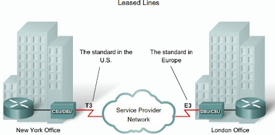
Leased Lines
When permanent dedicated connections are required, a point-to-point link is used to provide a pre-established WAN communications path from the customer premises through the provider network to a remote destination. Point-to-point lines are usually leased from a carrier and are called leased lines.
Leased lines are available in different capacities and are generally priced based on the bandwidth required and the distance between the two connected points.
Point-to-point links are usually more expensive than shared services such as Frame Relay. The cost of leased line solutions can become significant when they are used to connect many sites over increasing distances. A router serial port is required for each leased line connection. A CSU/DSU and the actual circuit from the service provider are also required.
Leased lines provide permanent dedicated capacity and are used extensively for building WANs. They have been the traditional connection of choice but have a number of disadvantages. Leased lines have a fixed capacity; however, WAN traffic is often variable leaving some of the capacity unused. In addition, each endpoint needs a separate physical interface on the router, which increases equipment costs


Analog Dialup
Traditional telephony uses a copper cable, called the local loop, to connect the telephone handset in the subscriber premises to the CO. The signal on the local loop during a call is a continuously varying electronic signal that is a translation of the subscriber voice, analog.
Traditional local loops can transport binary computer data through the voice telephone network using a modem. The modem modulates the binary data into an analog signal at the source and demodulates the analog signal to binary data at the destination. The physical characteristics of the local loop and its connection to the PSTN limit the rate of the signal to less than 56 kb/s
Integrated Services Digital Network
Integrated Services Digital Network (ISDN) is a circuit-switching technology that enables the local loop of a PSTN to carry digital signals, resulting in higher capacity switched connections. ISDN changes the internal connections of the PSTN from carrying analog signals to time-division multiplexed (TDM) digital signals. TDM allows two or more signals or bit streams to be transferred as subchannels in one communication channel. The signals appear to transfer simultaneously, but physically are taking turns on the channel. A data block of subchannel 1 is transmitted during timeslot 1, subchannel 2 during timeslot 2, and so on. One TDM frame consists of one timeslot per subchannel.
ISDN turns the local loop into a TDM digital connection. This change enables the local loop to carry digital signals that result in higher capacity switched connections. The connection uses 64 kb/s bearer channels (B) for carrying voice or data and a signaling, delta channel (D) for call setup and other purposes.
There are two types of ISDN interfaces:
- Basic Rate Interface (BRI)-ISDN is intended for the home and small enterprise and provides two 64 kb/s B channels and a 16 kb/s D channel. The BRI D channel is designed for control and often underused, because it has only two B channels to control. Therefore, some providers allow the D channel to carry data at low bit rates, such as X.25 connections at 9.6 kb/s.
- Primary Rate Interface (PRI)-ISDN is also available for larger installations. PRI delivers 23 B channels with 64 kb/s and one D channel with 64 kb/s in North America, for a total bit rate of up to 1.544 Mb/s. This includes some additional overhead for synchronization. In Europe, Australia, and other parts of the world, ISDN PRI provides 30 B channels and one D channel, for a total bit rate of up to 2.048 Mb/s, including synchronization overhead. In North America, PRI corresponds to a T1 connection. The rate of international PRI corresponds to an E1 or J1 connection.
ISDN is also used as a backup if the leased line fails. ISDN tariffs are based on a per-B channel basis and are similar to those of analog voice connections.

Common Packet Switching WAN Technologies
The most common packet-switching technologies used in today's enterprise WAN networks include Frame Relay, ATM, and legacy X.25.
X.25
X.25 is a legacy Network layer protocol that provides subscribers with a network address. Virtual circuits can be established through the network with call request packets to the target address. The resulting SVC is identified by a channel number. Data packets labeled with the channel number are delivered to the corresponding address. Multiple channels can be active on a single connection.
Typical X.25 applications are point-of-sale card readers. These readers use X.25 in dialup mode to validate transactions on a central computer. X.25 link speeds vary from 2400 b/s up to 2 Mb/s. However, public networks are usually low capacity with speeds rarely exceeding above 64 kb/s.

Frame Relay
Although the network layout appears similar to X.25, Frame Relay differs from X.25 in several ways. Most importantly, it is a much simpler protocol that works at the Data Link layer rather than the Network layer. Frame Relay implements no error or flow control. The simplified handling of frames leads to reduced latency, and measures taken to avoid frame build-up at intermediate switches help reduce jitter. Frame Relay offers data rates up to 4 Mb/s, with some providers offering even higher rates.
Frame Relay VCs are uniquely identified by a DLCI, which ensures bidirectional communication from one DTE device to another. Most Frame Relay connections are PVCs rather than SVCs.
Frame Relay provides permanent, shared, medium-bandwidth connectivity that carries both voice and data traffic. Frame Relay is ideal for connecting enterprise LANs. The router on the LAN needs only a single interface, even when multiple VCs are used. The short-leased line to the Frame Relay network edge allows cost-effective connections between widely scattered LANs.

ATM
Asynchronous Transfer Mode (ATM) technology is capable of transferring voice, video, and data through private and public networks. It is built on a cell-based architecture rather than on a frame-based architecture. ATM cells are always a fixed length of 53 bytes. The ATM cell contains a 5 byte ATM header followed by 48 bytes of ATM payload. Small, fixed-length cells are well suited for carrying voice and video traffic because this traffic is intolerant of delay. Video and voice traffic do not have to wait for a larger data packet to be transmitted.
The 53 byte ATM cell is less efficient than the bigger frames and packets of Frame Relay and X.25. Furthermore, the ATM cell has at least 5 bytes of overhead for each 48-byte payload. When the cell is carrying segmented Network layer packets, the overhead is higher because the ATM switch must be able to reassemble the packets at the destination. A typical ATM line needs almost 20 percent greater bandwidth than Frame Relay to carry the same volume of Network layer data.
ATM was designed to be extremely scalable and can support link speeds of T1/E1 to OC-12 (622 Mb/s) and higher. ATM offers both PVCs and SVCs, although PVCs are more common with WANs. And as with other shared technologies, ATM allows multiple VCs on a single leased-line connection to the network edge.

Broadband Services
Broadband connection options are typically used to connect telecommuting employees to a corporate site over the Internet. These options include cable, DSL, and wireless.
DSL
DSL technology is an always-on connection technology that uses existing twisted-pair telephone lines to transport high-bandwidth data, and provides IP services to subscribers. A DSL modem converts an Ethernet signal from the user device to a DSL signal, which is transmitted to the central office.
Multiple DSL subscriber lines are multiplexed into a single, high-capacity link using a DSL access multiplexer (DSLAM) at the provider location. DSLAMs incorporate TDM technology to aggregate many subscriber lines into a single medium, generally a T3 (DS3) connection. Current DSL technologies use sophisticated coding and modulation techniques to achieve data rates of up to 8.192 Mb/s.

Cable Modem
Coaxial cable is widely used in urban areas to distribute television signals. Network access is available from some cable television networks. This allows for greater bandwidth than the conventional telephone local loop.
Cable modems provide an always-on connection and a simple installation. A subscriber connects a computer or LAN router to the cable modem, which translates the digital signals into the broadband frequencies used for transmitting on a cable television network. The local cable TV office, which is called the cable headend, contains the computer system and databases needed to provide Internet access. The most important component located at the headend is the cable modem termination system (CMTS), which sends and receives digital cable modem signals on a cable network and is necessary for providing Internet services to cable subscribers.
All the local subscribers share the same cable bandwidth. As more users join the service, available bandwidth may be below the expected rate.

Broadband Wireless
Wireless technology uses the unlicensed radio spectrum to send and receive data. The unlicensed spectrum is accessible to anyone who has a wireless router and wireless technology in the device they are using.
Until recently, one limitation of wireless access has been the need to be within the local transmission range (typically less than 100 feet) of a wireless router or a wireless modem that has a wired connection to the Internet. The following new developments in broadband wireless technology are changing this situation:
- Municipal WiFi
- WiMAX
- Satellite Internet

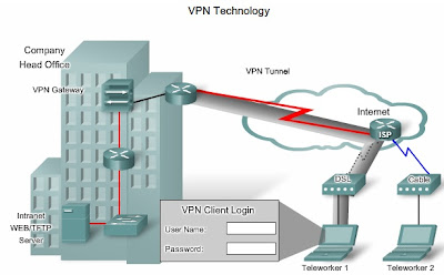
VPN Technology
A VPN is an encrypted connection between private networks over a public network such as the Internet. Instead of using a dedicated Layer 2 connection such as a leased line, a VPN uses virtual connections called VPN tunnels, which are routed through the Internet from the private network of the company to the remote site or employee host.
Benefits of VPN include the following:
- Cost savings-VPNs enable organizations to use the global Internet to connect remote offices and remote users to the main corporate site, thus eliminating expensive dedicated WAN links and modem banks.
- Security-VPNs provide the highest level of security by using advanced encryption and authentication protocols that protect data from unauthorized access.
- Scalability-Because VPNs use the Internet infrastructure within ISPs and devices, it is easy to add new users. Corporations are able to add large amounts of capacity without adding significant infrastructure.
- Compatibility with broadband technology-VPN technology is supported by broadband service providers such as DSL and cable, so mobile workers and telecommuters can take advantage of their home high-speed Internet service to access their corporate networks. Business-grade, high-speed broadband connections can also provide a cost-effective solution for connecting remote offices
There are two types of VPN access:
- Site-to-site VPNs-Site-to-site VPNs connect entire networks to each other, for example, they can connect a branch office network to a company headquarters network. Each site is equipped with a VPN gateway, such as a router, firewall, VPN concentrator, or security appliance.

- Remote-access VPNs-Remote-access VPNs enable individual hosts, such as telecommuters, mobile users, and extranet consumers, to access a company network securely over the Internet. Each host typically has VPN client software loaded or uses a web-based client.

Metro Ethernet
Metro Ethernet is a rapidly maturing networking technology that broadens Ethernet to the public networks run by telecommunications companies. IP-aware Ethernet switches enable service providers to offer enterprises converged voice, data, and video services such as IP telephony, video streaming, imaging, and data storage. By extending Ethernet to the metropolitan area, companies can provide their remote offices with reliable access to applications and data on the corporate headquarters LAN.
Benefits of Metro Ethernet include:
- Reduced expenses and administration-Metro Ethernet provides a switched, high-bandwidth Layer 2 network capable of managing data, voice, and video all on the same infrastructure.
- Easy integration with existing networks-Metro Ethernet connects easily to existing Ethernet LANs, reducing installation costs and time.
- Enhanced business productivity-Metro Ethernet enables businesses to take advantage of productivity-enhancing IP applications that are difficult to implement on TDM or Frame Relay networks, such as hosted IP communications, VoIP, and streaming and broadcast video.


Nessun commento:
Posta un commento